Introduction
Fire -fighting is a dangerous job to do, sometimes firemen do their best to save someone’s life but unfortunately they lose their. Moreover it is impossible for a fireman to reach some places when it exceeds a certain level of temperature but a robot can. That is why fire-fighting robots start to appear in real life. That was my inspiration of my project as I wanted to solve this problem. – Karim –
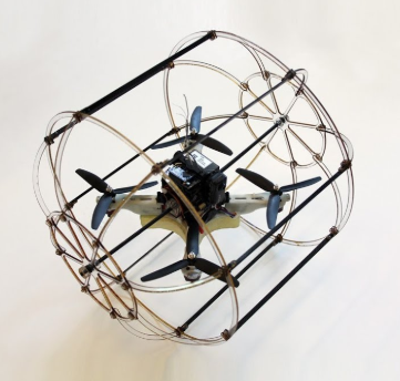
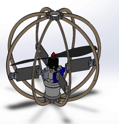
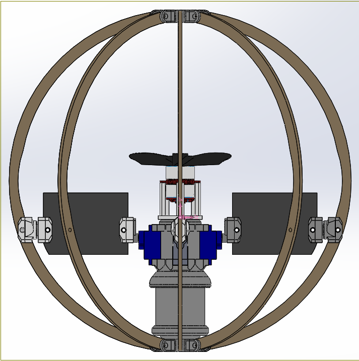
The proposed robot is an Unmanned Aerial Vehicle (UAV). I am a part from two person team that is working on this project. My part is to fully control the mechanical design made by my teammate Ahmed. Our UAV has a spherical design which is unique in drones. it has the ability to fly in-doors due to its small size, farther more all its components are maintained in a spherical cage to make its movement safe also to protect its internal structure from any damage my occur. It can be used for in-doors fire-fighting and inspection. – Karim –
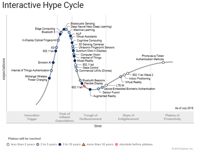
According to this hype cycle from Gartner it shows that UAVs technology is on Trough of Disillusionment region which means that the Interest wanes as experiments and implementations fail to deliver but my interest did not yet, As I am expecting this field will be mature enough in the next few years. – Karim –
Previously the concept of fire-fighting robots did not exist as it was impossible to totally depend on a robot to extinguish even a small fire due to high nonlinearity of the sensors and low efficiency of the overall technique. Nowadays with the advanced techniques it is possible to fully control the robot from a distant. With the help of such robots, fireman can do his job from a safe zone if it is not possible for him to enter. Moreover when this robot is an UAV that can fly between fires flames searching for a soul to rescue, that facilitates the process of fire-fighting with high degree. The proposed fire-fighting robot is an UAV that is remotely controlled from a few meters away from the fire. UAVs are mainly tested nowadays in fire-fighting, some of it is used to explore the site of the fire only to rescue any soul, and the others may participate in the process of fire-fighting itself for example forests fires. – Karim –
Background of UAVs
The use of unmanned aerial vehicles (UAVs) is growing rapidly across many civil application domains including real-time monitoring, providing wireless coverage, remote sensing, search and rescue, delivery of goods, security and surveillance, precision agriculture, and civil infrastructure inspection. Smart UAVs are the next big revolution in UAV technology promising to provide new opportunities in different applications, especially in civil infrastructure in terms of reduced risks and lower cost. Civil infrastructure is expected to dominate more than $45 Billion market value of UAV usage. (Dspace.lib.cranfield.ac.uk, 2019) -Ahmed-
Unmanned vehicles can be classified into five different types according to their operation. These five types are unmanned ground vehicles, unmanned aerial vehicles, unmanned surface vehicles (operating on the surface of water), unmanned underwater vehicles, and unmanned spacecrafts. Unmanned vehicles can be either remote guided or autonomous vehicles. -Ahmed-
This blog presents a detailed comparison of different design approaches of spherical UAVs, a new design approach using contra rotating motors, motor sizing, initial cost, project timeline, and testing done on this design. Spherical UAVs presents a new design approach that can operate in closed environments such as tunnels, caves or building. It is motored by one co-axial contra rotating motor that minimizes the torque effect. Flaps are included in the design to control the up/down, roll, pitch and yaw. And all the body is enclosed in a sphere-shaped design to protect the propellers. -Ahmed-

Indoor environments present other type of operational challenges such as restricted space for maneuvering, GPS coverage, and the number of obstacles present in the operational environment. Several researchers have focused their research interest on fabricating smaller and more adaptive UAV designs to minimize the collision impact and increase the mission effectiveness in an indoor environment. However, another approach is to investigate and research the development of more innovative aerial vehicle designs and configurations. Parrot (2015) and Kalantari and Spenko (2013), presented two UAVs with similar design concepts that have a special frame, which allows the platform of performing both aerial and terrestrial locomotion in challenging terrains. A spherical UAV, developed by the Japanese Defense Technical Research and Development Institute, was reported by Jonsson (2011). This vehicle is capable of flying in cramped and cluttered environments. -Ahmed-
There is no risk of propeller damage, since they are protected inside the structure. (Arcweb.com, 2019).The spherical UAV is intended for firefighting applications, providing a low cost, sacrificial, and an easy to control unit for such an application, the design is very challenging because unlike the normal quadrotor, a spherical design is vulnerable to moment inertia due to gyroscopic effect, mainly because of the spinning rotor moment of inertia, the main frame of the sphere would resist this moment by another moment which will cause the sphere to flip on its side. Resulting to incomplete balance. -Ahmed-

Project planning and scheduling
In order to achieve our goal the following plan has been made and it is classified into several stages.
- Researching – Team –
- Motor sizing
- Mechanical Design – Ahmed –
- Programming – Karim –
- Circuit Implementation – Karim –
- Components Assembly – Ahmed –
- Testing & troubleshooting – Team –
- Improving – Team –
The following Gantt chart has been made to make sure that we are on track.
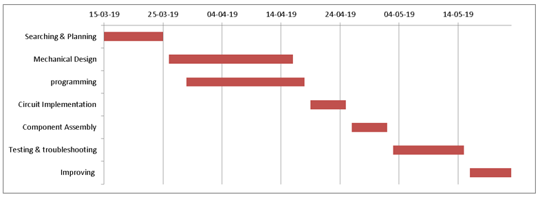
Gantt chart
Researching
First of all I had to choose the microcontroller I am going to use. Although it was a little bit challenging to use Arduino Nano due to its weak processor that may be not able to handle the algorithm I am going to use, I took the risk. Then I had to choose the components I am going to use and search how to control it. – Karim –
Our system is mainly consists of:
- Brushless motor that rotates propellers for the vertical motion.
- 3D printed flaps when its angular position change the drone moves horizontally.
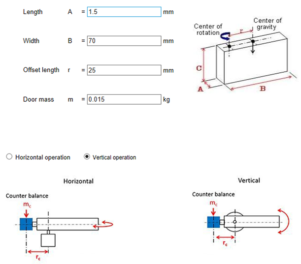
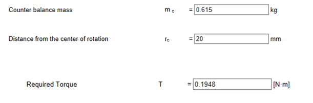
Therefore I had to know how to drive the brushless motor also how to control the angular position of the flaps. For the motor, we are using a coaxial Contra-Rotating motor that is actually two brushless motors rotating against each other to cancel the effect of the moment done by the spherical drone itself. Therefore I needed two ECS (Electronic Speed Control) to drive this motor. For the flaps I used four servo motors to control their angular positions in order to perform yaw, pitch and roll movements. Before moving to the next stage some calculations had to be made for servo motors selections to ensure that they can sustain thrust force exerted by the brushless motor. By knowing the thrust value of the motor and the flaps dimensions it was found that a torque of 1.9 Kg.cm is required to perform this job. – Karim –
My second step was to control the ESCs, it needs a PWM signal of 50 Hz (20 ms) as well as servo motors which means that I can use the same motor driver to drive 4 servo motors and 2 ESCs which is a good thing for me. Therefore I chose pca9685 which is an motor driver that can drive up to 16 servo motor and it is connected to the Arduino via I2C communication protocol while it gets power (5V) from an external power source. – Karim-


regarding to mechanical design, a great approach for such a challenge was the innovative design made by the Japanese defence technical research and development institute. This design mainly focuses on contra rotating motor effect, which can be seen in Helicopters. A two coaxial rotating propellers in opposite directions will provide the necessary thrust force for operation and will neglect the moment of inertia produced by the gyroscopic effect. -Ahmed-
The idea is rather simple. Two in-line propellers turning in opposite directions. There are two main advantages to this:
-The props spinning in opposite directions cancels out any torque that would otherwise be sent back into the airplane.
-Efficiency. The accelerated air from the fore prop allows the after prop to perform the same work with less energy and in so accelerates the air further. The efficiency is measured by an increment of thrust force, and reduction of power used the data can be shown below that compares contra rotating motors mounted on the same axis, side by side motors, and overlapping motors. The test checks how much power for each configuration of multi rotors to provide 10 ounces, 1 pound, and 2 pounds of thrust. -Ahmed-
This test is provided by rctestflight channel on youtube link: https://www.youtube.com/watch?v=tFJyE3Uns3o

the data shows that coaxial motors Is better than normal configuration and overcomes the overlapping configuration in minimizing the torque effect, and space usage. – Ahmed-
Providing enough torque to turn the flaps, a rotation around the x-axis will need two of flaps to move. A rotation around the y-axis will require the two opposite flaps to move. A rotation around z-axis will require a different speed of both propellers to produce enough torque to turn the sphere. (Sun, Hou and Jia, 2019). -Ahmed-
Motor sizing
Following a detailed comparison for contra rotating motors, comparison base on static thrust, dimensions, price, and power consumption.
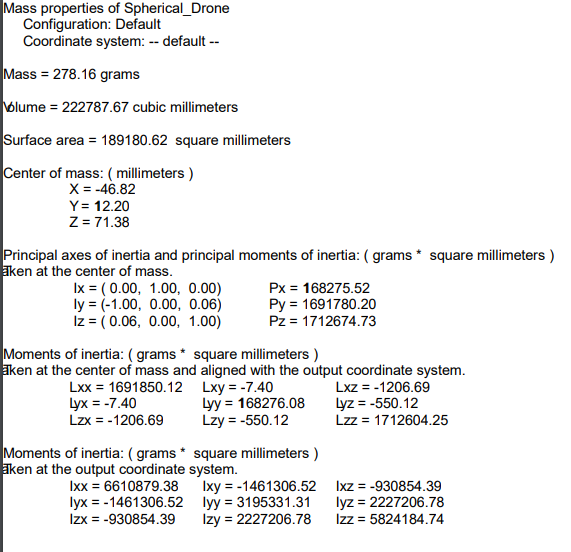
-net mass of the spherical UAV mechanical design reached 278 grams, given manufacturing error of 10%, then a net mass of 305 grams is reached, means that there is a mass of 694.2 grams for (ESCs, Battery, Servos, control board and camera) -Ahmed-
-components of gravity equations can be expressed as following:
Which means that FG will not exceed 11.772 N.
-components
-Lift force equations:
The main problem in these equations is the calculation of the induced velocity of air after the propeller, and because it needs a very detailed CFD analysis, we managed to find another equation for thrust force calculation. -Ahmed-

And because for the drone to rise, it needs a thrust/weight ratio > 1.
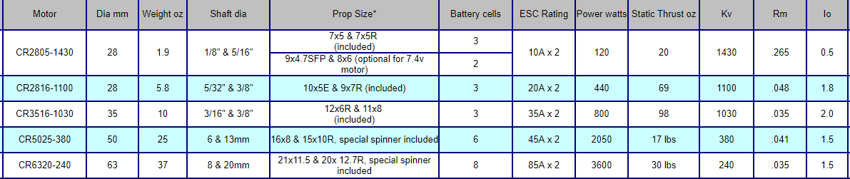
By comparing the contra rotating motor modules in market, we found two main brands works in them (HIMAX, and AEO).
Best of AEO motors can reach a static thrust of 1400 gram, which will be risky because it won’t make enough room for spherical drone to accelerate. -Ahmed-
AEO Best Thrust to Weight Motor
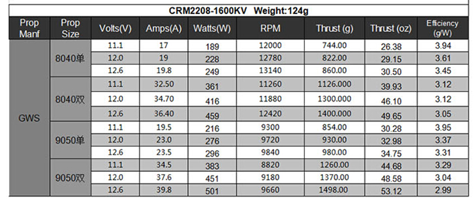
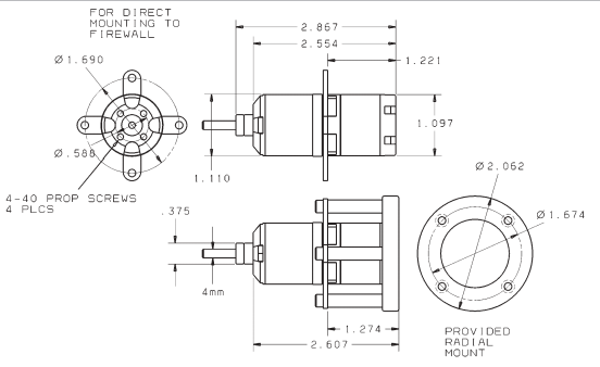
HIMAX(http://www.maxxprod.com/mpi/mpi-266.html) produce 4 different sizes of contra rotating motors, ranges from 5N static thrust to 67N, different sizes of propellers and motors are taken into consideration, and following results is found for model CRM2816:
Static Thrust for RPM of 8000-9500, which can be achieved on 16-21 AMP is 17.8 N, this data is achieved by using two propellers one 9*7 where 9 is the outer diameter in inches, 7 is the pitch of the propeller, and other one of 10*5. -Ahmed-
HIMAX Motors Thrust Data
Upon these results a thrust to weight ratio of 1.52 is achieved.
After deciding which motor to be used we checked the availability of this product to be delivered to UK in the shortest period, unfortunately we found a supplier who can deliver the motor to our lap, but in one month, which was not conforming with our timetable. As a result, we went for the AEO motors, which we found on hobbyking (https://hobbyking.com/en_us/cr23s-contra-rotating-bl-system-1700kv.html) and will be supplied to our address in 10 days, which was acceptable because it was the only feasible solution. -Ahmed-
The motor we found has the following data
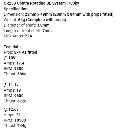
This made us re-calculate our thrust force, and upon the result we changed our sphere mass to reach 220 grams maximum without any electrical components, batteries or ESCs.
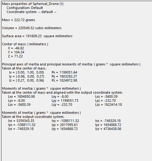
A new challenge was there for the mechanical design which is to implement a new design that will not exceed 220 grams, following a comparison between initial design and second design mass properties. -Ahmed-
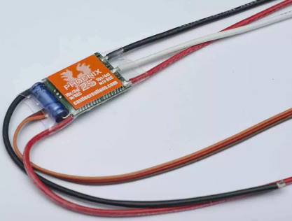
- ESC rating:
Following the motor manufacturer, the ESC rating for the motor should be 20A, or 25 A for each motor.
This means that each motor will require at least 16-20 A of continuous current, and maximumly can reach 25A on full load.
For safety of motor, a current of 25A should not be exceeded, and ESC works as a controller and as well as a protection device of overcurrent, so we found 5 ESCs rated to 30AMPs, and only cost us 15pounds, which was a good thing, most importantly that ESCs took 2 days to arrive, compared to the pheniox ESCs that would take 1 Month. -Ahmed-
-Power consumption and battery:
Depending on the chosen motor, and required voltage of 12.1 volt is required for the motor performance we had the only choice of LIPO batteries, following calculations has been considered:
-two motor amperes drawn on full load = 22 AMP
-other control components will require less than 500mah, which means they can be connected to ESC power plug.
-an operation time of 10 mins on full load is wanted
With the above specifications a desired LIPO battery with capacity of 6000mah is required for 10 mins flying on full throttle. This result will lead to dimensions inaccuracy, non-aerodynamic shape, and of course excess of weight.
Dimensions of 6000mah battery is (120mm*37mm*35mm) and has a mass of 550 grams, which is exactly the half of the drone mass.
-other considerations of smaller batteries and flight time is compared as shown:
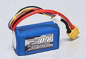
800mah:28mm*26mm*45mm, operation time of 1.2 minutes
1200mah: 26mm*32mm*76mm, operation time of 1.8 minutes
1550mah: 26mm*32mm*80mm, operation time of 2.25 minutes
2200mah: 26mm*32mm*100mm, operation time of 3.3 minutes
3000mah: 26mm*32mm*105mm, operation time of 4.5minutes
For the dimensions, and considering a case of only 50% of throttle will be used in the real flight, an 800mah battery is used -Ahmed-
Mechanical design
-Design Requirements:
-Lightweight spherical drone <1000 gm.
-using coaxial motors for torque elimination and easy control.
-ability to manoeuvre inside buildings.
-has a space for camera modules to be fixed on it.
-low cost < 300 GDP.
-easy to manufacture
-easy to assemble.
We decided the design requirements upon the time available, manufacturing tools, coaxial motors available in UK, and mathematical calculations of thrust force required, flaps are required for actuation forces, and power usage. -Ahmed-
Mainly we were searching for a design that can be manufactured using 3d printing, CNC laser cutting on low density materials such as foam, or plywood. Additionally, the design needed to be assembled in the least number of steps, with the least number of mounts or fixations such as bolts or bearings, which made us bay attention to fits and tolerances across PLA material, and PLY wood. -Ahmed-
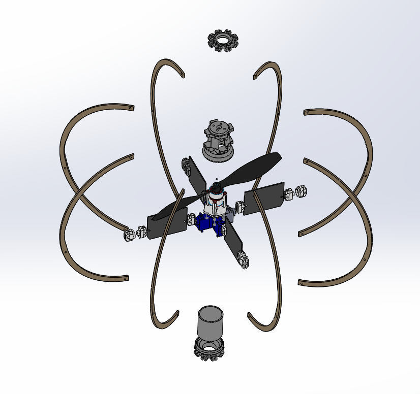
Some of the designs we looked for online are shown below, almost all the designs are using co-axial contra rotating motors for providing the trust force required, and flaps actuated by servo motors, and a shell to protect the propellers. -Ahmed-
Some of the designs such as Fleye considers fixed sphere frame to protect the propellers, other designs propose that the outer sphere rotates around 2 axis, such an approach enables the UAV to manoeuvre on the ground with ease, but limits the space needed for fixing additional modules. -Ahmed-


-CAD phase:
Depending on the motor dimensions shown, and design considerations of spherical UAV have been taken into consideration like lightweight, easy to control the rudders, and low-cost material to be used. -Ahmed-
We started with existing model shown below from will Cogley channel on YouTube: https://www.youtube.com/channel/UCkUD_8b1JoTL2ipOVtxfNKw
And then we managed to change the main dimensions and fixation for the motor, extended the outer frame to occupy the propellers with ease, and enlarged the bottom cylinder to occupy the control and power circuit. -Ahmed-
Noted to the design is the aerodynamic shape, which consists of cylinders attached to each other, chamfers and fillets are required for more aerodynamic shape as shown:
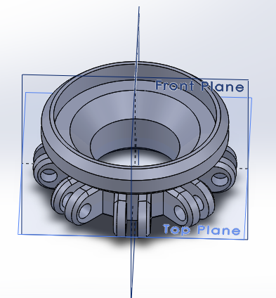
We started manufacturing the parts on a 3d printer, and CNC laser cutting machine, materials used was PLA, and MDF 3mm in thickness. -Ahmed-
Programming

I am using C language to program our microcontroller (Arduino Nano). My target was to receive the signal sent from RC transmitter and give it to our actuators (four servos and two ESCs) also to make a self-balancing program for the sphere using PID control. – Karim-
- Receiving transmitter signal
The RC transmitter we are using sends a PWM signal among 10 channels. I used an interruption that detects the change in the state (high or low) of the digital pins I am using and calculates the time between each change. Therefore I am expecting values between (1000 to 2000 micro seconds). This way I am able to know the magnitude of the PWM signal sent by the transmitter. -Karim-
ISR(PCINT0_vect){
//First we take the current count value in micro seconds using the micros() function

  current_count = micros();
  ///////////////////////////////////////Channel 1
  if(PINB & B00000001){                              //We make an AND with the pin state register, We verify if pin 8 is HIGH???
    if(last_CH1_state == 0){                         //If the last state was 0, then we have a state change...
      last_CH1_state = 1;                            //Store the current state into the last state for the next loop
      counter_1 = current_count;                     //Set counter_1 to current value.
    }
  }
  else if(last_CH1_state == 1){                      //If pin 8 is LOW and the last state was HIGH then we have a state change
    last_CH1_state = 0;                              //Store the current state into the last state for the next loop
    input_ROLL = current_count - counter_1;   //We make the time difference. Channel 1 is current_time - timer_1.
  }
- PID control
PID control is being used to solve the imperfection of the mechanical design by making the sphere has the ability to balance itself by changing the angle of the flaps to keep its desired position. -Karim-
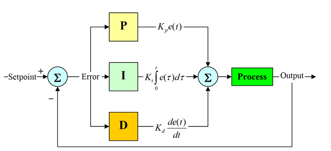
The set point of the system is the sensor reading while the sphere is in its ordinary vertical position. I am using gyroscope sensor for the feedback of this system, it gives the angle of deviation over X, Y and Z axis. By knowing these angles the error can be calculated, which is the difference between the set point and the instant reading of the sensor. After knowing the error, the three parameters are being calculated (P, I and D) using these formulas. -Karim-
P = Kp * error
I = pid_i + (Ki*error)
D = Kd*((error – previous_error)/elapsedTime)
Where Ki, Kp and Kd are constants usually defined by try and error method. Knowing that Kp is responsible for system response speed, Ki stands for Integral action and applies correction based upon how long the error exists and Kd stands for Derivative action and applies correction based upon how fast the error is changing. -Karim-
For the feedback of the system I am using IMU sensor MPU-6050 which is a gyroscope and accelerometer in the same chip. This chip is the most common one used in drones due to its high sensitivity and accuracy. -Karim-
Here is the part of the code that is used to get accurate readings from the sensor:
 Acc_rawX=Wire.read()<<8|Wire.read(); //each value needs two registres
     Acc_rawY=Wire.read()<<8|Wire.read();
     Acc_rawZ=Wire.read()<<8|Wire.read();


    /*///This is the part where you need to calculate the angles using Euler equations///*/

    /* - Now, to obtain the values of acceleration in "g" units we first have to divide the raw
     * values that we have just read by 16384.0 because that is the value that the MPU6050
     * datasheet gives us.*/
    /* - Next we have to calculate the radian to degree value by dividing 180º by the PI number
    * which is 3.141592654 and store this value in the rad_to_deg variable. In order to not have
    * to calculate this value in each loop we have done that just once before the setup void.
    */

    /* Now we can apply the Euler formula. The atan will calculate the arctangent. The
     *  pow(a,b) will elevate the a value to the b power. And finnaly sqrt function
     *  will calculate the rooth square.*/
     /*---X---*/
     Acceleration_angle[0] = atan((Acc_rawY/16384.0)/sqrt(pow((Acc_rawX/16384.0),2) + pow((Acc_rawZ/16384.0),2)))*rad_to_deg;
     /*---Y---*/
     Acceleration_angle[1] = atan(-1*(Acc_rawX/16384.0)/sqrt(pow((Acc_rawY/16384.0),2) + pow((Acc_rawZ/16384.0),2)))*rad_to_deg;

   /*Now we read the Gyro data in the same way as the Acc data. The adress for the
    * gyro data starts at 0x43. We can see this adresses if we look at the register map
    * of the MPU6050. In this case we request just 4 values. W don¡t want the gyro for
    * the Z axis (YAW).*/

   Wire.beginTransmission(0x68);
   Wire.write(0x43); //Gyro data first adress
   Wire.endTransmission(false);
   Wire.requestFrom(0x68,4,true); //Just 4 registers

   Gyr_rawX=Wire.read()<<8|Wire.read(); //Once again we shif and sum
   Gyr_rawY=Wire.read()<<8|Wire.read();

   /*Now in order to obtain the gyro data in degrees/seconda we have to divide first
   the raw value by 131 because that's the value that the datasheet gives us*/

   /*---X---*/
   Gyro_angle[0] = Gyr_rawX/131.0;
   /*---Y---*/
   Gyro_angle[1] = Gyr_rawY/131.0;

   /*Now in order to obtain degrees we have to multiply the degree/seconds
   *value by the elapsedTime.*/
   /*Finnaly we can apply the final filter where we add the acceleration
   *part that afects the angles and ofcourse multiply by 0.98 */

   /*---X axis angle---*/
   Total_angle[0] = 0.98 *(Total_angle[0] + Gyro_angle[0]*elapsedTime) + 0.02*Acceleration_angle[0];
   /*---Y axis angle---*/
   Total_angle[1] = 0.98 *(Total_angle[1] + Gyro_angle[1]*elapsedTime) + 0.02*Acceleration_angle[1];

   /*Now we have our angles in degree and values from -10º0 to 100º aprox*/
Mixing PID output with transmitter signal
There are two ways to prevent the output PID value from interfering with the signal sent from the transmitter to protect the servo motors from any unreasonable signal. The first way is to turn off the PID control while giving any signals from the RC transmitter, this may work with a quad copter due to its smooth motion. But In our case, when I turn off the PID control the sphere becomes very unstable. Therefore I had to mix both signals of the PID and the transmitter by adding the two values and merging them in one value with a condition that it prevents it from exceeding the maximum signal realized by the servos or sending a value below the minimum. -Karim-
x = Output_x + input_PITCH; // adding PID value of x-axis and input pitch from the transmitter
if ( x > 2000 )
x = 2000;

if ( x < 1000 )
x = 1000;

x_servo= map (x, 1000,2000,520,230); // mapping the values to values realized by servo driver
    pwm.setPWM(servo1, 0, x_servo);
x_servo= map (x, 1000,2000,230,520);
    pwm.setPWM(servo2, 0, x_servo);

y = Output_y + input_ROLL; // adding PID value of y-axis and input roll from the transmitter

if ( y > 2000 )
y = 2000;

if ( y < 1000 )
y = 1000;

y_servo= map (y, 1000,2000,520,230); // mapping the values to values realized by servo driver
    pwm.setPWM(servo3, 0, y_servo);
y_servo= map (y, 1000,2000,230,520);
    pwm.setPWM(servo4, 0, y_servo);
Circuit implementation
Our circuit consists of:
- Arduino Nano
- RC receiver
- Motors driver
- Buck converter
- Gyroscope sensor
- Lipo battery
Here are the schematic connections for the components. -Karim-
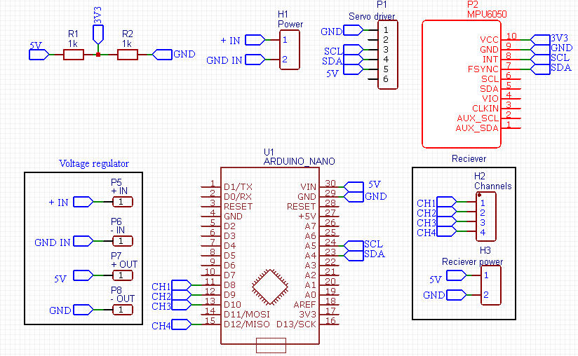
Our power source is a lipo battery of 2200 mAh with 12V output voltage, which is the nominal voltage of the ESCs but for the electronics, their operating voltage is 3V~5V. This means that we need a buck converter that step down the voltage from 12V to 5V to supply all the electronics and servomotors except for the gyroscope sensor which is MPU-6050 that operates at 3.3V. That’s why I used voltage divider method using two resistances to covert 5V to 3.3V. -Karim-
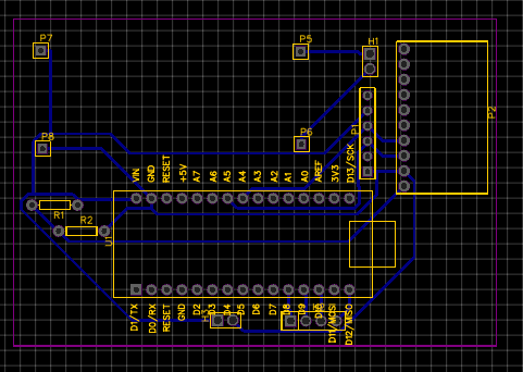

After getting the PCB done and connecting DC buck converters, i tested the whole circuit on 12 volt input.
By reaching this stage, my control system is ready to be implemented in the mechanical design to perform our first test. -Karim-
Testing & troubleshooting
Our first test after the mechanical design assembly and circuit implementation was actually an open loop system test to notice its response without PID control. Honestly the response was not pleasing at all. -Karim-
I did give the ESCs the signal of the full thrust of the motor and body was not stable at all after exceeding 50% of the motor thrust force. -Karim-
Therefore using PID control is certain. Using Ziegler Nichols method I started to increase Kp gradually until the system response became acceptable then Ki and Kd. Then I tested PID response without flying the drone (stationary test). -Karim-
The first PID stationary test shows that the system response still not fast enough to compensate the errors. -Karim-
By decreasing Kd the response started to be faster and here are the results
After adding PID control, it was able to make the sphere stable till 80% of the motor thrust force which is considered a progress. Unfortunately that was not enough to make the drone flies. Therfore we had to do some improvements. -Karim-
Improving
first design trial had a lot of issues such as
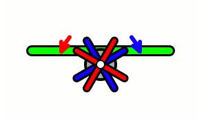
-putting all the assembly into one centerline:
This happens because on the design there was no one line between the upper part and the bottom part of the sphere, which made it hard for us to determine the centerline of the assembly, this followed by undistributed loads around the center of mass of the sphere. -Ahmed-
-the motor mount was really below the center of the sphere, this made most of the weight of the UAV is far from the motor and exactly on the bottom of the sphere.
With the non-distributed load on the centerline of the design, and because the big distance between the center of mass of the sphere and the centerline of thrust force, moment effects was very obvious on the UAV while taking off. -Ahmed-
-the area of the flaps was not enough to provide actuating forces in the required angles, this was shown when the sphere was only able to move along x-axis or y-axis on minimum 70% of thrust force, which was not very efficient. -Ahmed-
-the motor was able to lift the sphere from it’s hanged position only when the trust forces reached 70-80% of the total thrust force, this made the sphere vulnerable to sudden lifting force and caused unbalance in the taking off period. -Ahmed-
as fast as possible the team members discussed the proper solutions to the problems appeared.
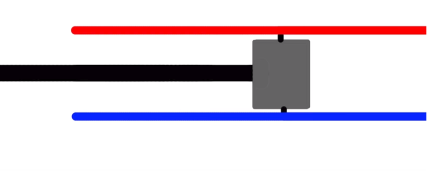
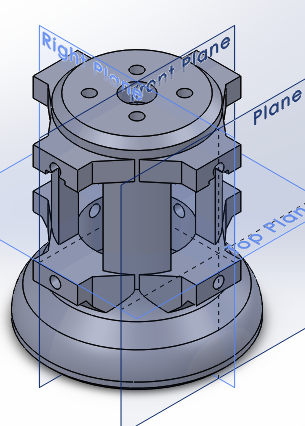
Suggested solutions were to bring the electronic enclosure up to the top of the sphere so that the center of mass ascends and the arm of the moment effect is minimized. we used Solidworks mass properties tool to measure the change of the position of the center of mass, according to weight distribution, after many trails we decided that putting the enclosure on the top is the perfect solution. As it brought the center of mass exactly below the coaxial motor. -Ahmed-
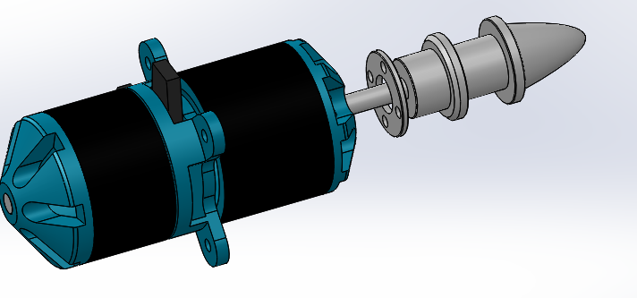
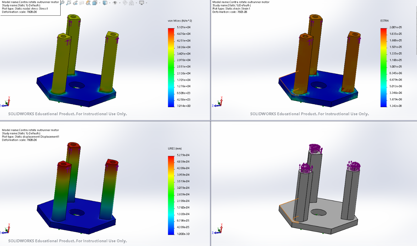
We then designed another part to hold the motor in place, this part needed to be aligned with ease with the servo motors holding the part, and to be high enough for the propellers to be slightly below the center point of the sphere. -Ahmed-
We draw the CAD model for this part as shown, and made a stress analysis on it with a force of 10N on each leg, and it held the stress and made an acceptable deformation level. -Ahmed-
Also a new assembly instructions were needed, because of the alignment problem, so we redesigned the parts tolerance, and adjusted the 3dprinter again for a tighter tolerance between parts, a successful method was to make an 8mm hole in each part, and align the parts according to the order from bottom and to the top. -Ahmed-
After this, an angle of inclination was measured, and it showed a result of -1 degree of inclination, which was very acceptable. -Ahmed-
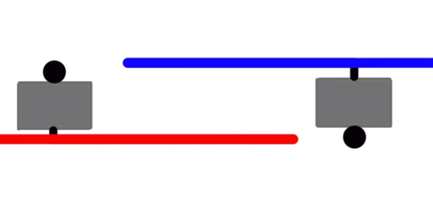
We thought about increasing the flaps are of contact to maximize the actuation force, and to increase the response time of sphere to the movement of the servo, as shown below the new and old size of the flaps. -Ahmed-
Such increment of the area by 17mm^2 which increase the actuation force by 0.2N per flap, this was enough for the sphere to change it’s behavior and response to flaps angles. -Ahmed-

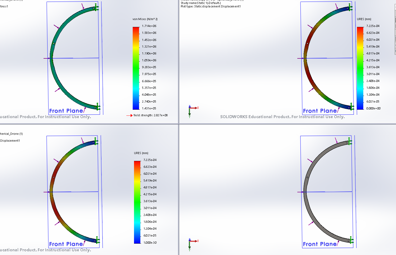
We thought about changing the design material to foam, as the foam has very low density, and the design at all will reach 50 grams at maximum, but the foam is vulnerable to hear and will be so hard to fit together as parts. Provided below strss analysis on the MDF spherical Rings. -Ahmed-

We measured the weight of the sphere after assembling all the parts, and it appeared to be 230 grams, which was a pretty decent margin of error for us.
We then started putting the electrical circuits in place, and enclose it under the body and started testing.
After the failure of our first design we tried to distribute the weight over the sphere to make its center of gravity in the middle as possible as we can. From the procedures that had to be made is to move the control box from the bottom of the sphere to its top. -Karim-
Lastly we did our final test after adjusting the design and the electronics fitting. Here is the result.
After the final test, the drone behavior was improved with high degree. it is almost flying but it still can not fly independant without being hanged. it still needs more improvement in the design in addtion to improving the response of the PID control. -Karim-
Conclusion
The thrust force of the motor used is not enough to handle the body’s weight even after removing the battery that weights 200 grams. – Karim-
Servos response to the PID signal is not fast enough to compensate the errors. -Karim-
working on the full thrust of the motor all the time is not a good idea, as motor temperature rises too much. -Karim-
In spherical drones; PID control is not enough to compensate the errors, the mechanical design must be the closest to perfection. -Karim-
Further Improvements
We are willing to improve our system by adjusting the mechanical design for the third time after knowing the last two mechanical designs issues. -Karim-
I am thinking of changing our micro controller due to its weak processor that cannot handle the speed of PID processing. -Karim-
We may add some sensors for fire-fighting participation and an IP camera for in-doors inspection. -Karim-
Reflections
After working in this project for 2 months, I gained good skills in circuit designing, programming skills and applying PID control system in real-life. That was an amazing experience and I am welling to keep working on it. -Karim-

